Work from the board outwards: the board maker's maximum span sets the joist spacing, the joist count sets the joist metres and tape, the support rate sets the pedestals or ground screws, and board rows × joists gives the number of fixing points. For a 5 × 4 m deck with joists at 400 mm, that is 14 joists (56 m), about 60–70 pedestals on a single layout or about 20 on a double layout, 3–4 rolls of joist tape and about 378 board crossings to fix. Add 5–10 % spare.
Test the system on your next deck Request samples of the tapes, screws, pedestals and foundations mentioned in our guides.
Request samples →Most quoting errors on decks are not in the boards. They are in the substructure: a forgotten row of supports, tape for the joists but not the bearers, or screws counted per square metre instead of per crossing. This guide shows how to calculate deck materials for the frame with one worked example, then turns it into a method a dealer or installer can reuse on every job.
Start with the board, not the frame
Everything below the boards follows from one figure: the maximum joist span in the board maker’s installation instructions. It sets the joist spacing, which sets the number of joists, which sets the supports, the tape and the fixings. Find that figure first. Typical ranges by board type are in deck joist spacing for timber, thermowood and composite boards.
Deck substructure material list for a 20 m² deck
Assumptions (change them to match your project):
- deck 5 m × 4 m on a level concrete slab, 20 m²;
- timber boards 145 mm wide with a 5 mm gap, so each row covers 150 mm;
- joists at 400 mm centres, running 4 m, spread across the 5 m width;
- boards running the full 5 m, so there are no board end joints in the field;
- support spacing along each joist checked against the joist supplier’s span table.
| Item | How it is counted | Example quantity |
|---|---|---|
| Joists | 5000 ÷ 400 = 12.5 → 13 spaces → 14 joists × 4 m | 14 pcs, 56 running metres |
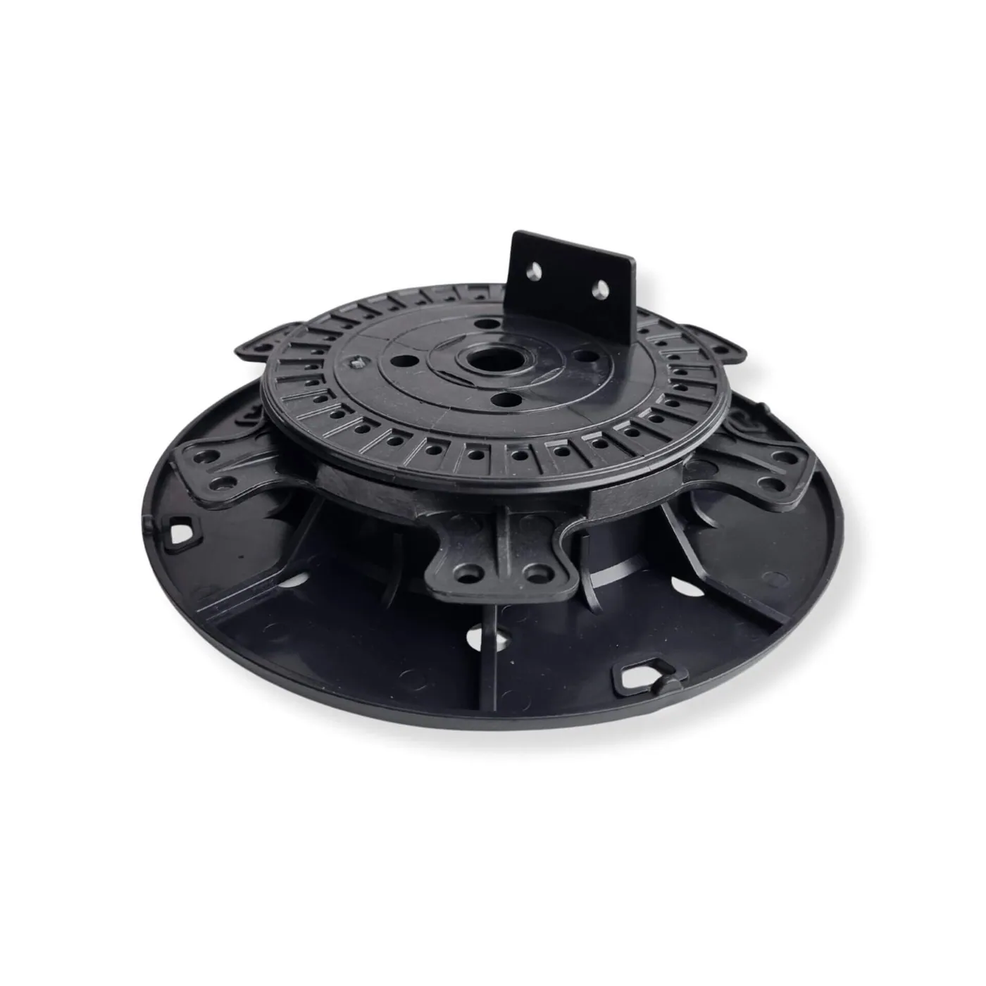
| Supports, single joist layout | 3–3.5 per m² (FT pedestals) | about 60–70 pedestals |
| Supports, double joist layout | about 1 per m² (FT pedestals or ground screws) | about 20, plus bearers |
| Support pads | one under each pedestal on slabs and membranes | same as pedestal count |
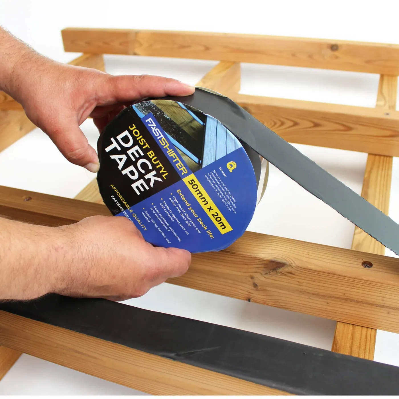
| Joist tape 50 mm | 56 m ÷ 20 m rolls = 2.8 | 4 rolls (3 leaves no spare) |
| Board crossings | 4000 ÷ 150 = 26.7 → 27 rows × 14 joists | 378 crossings |
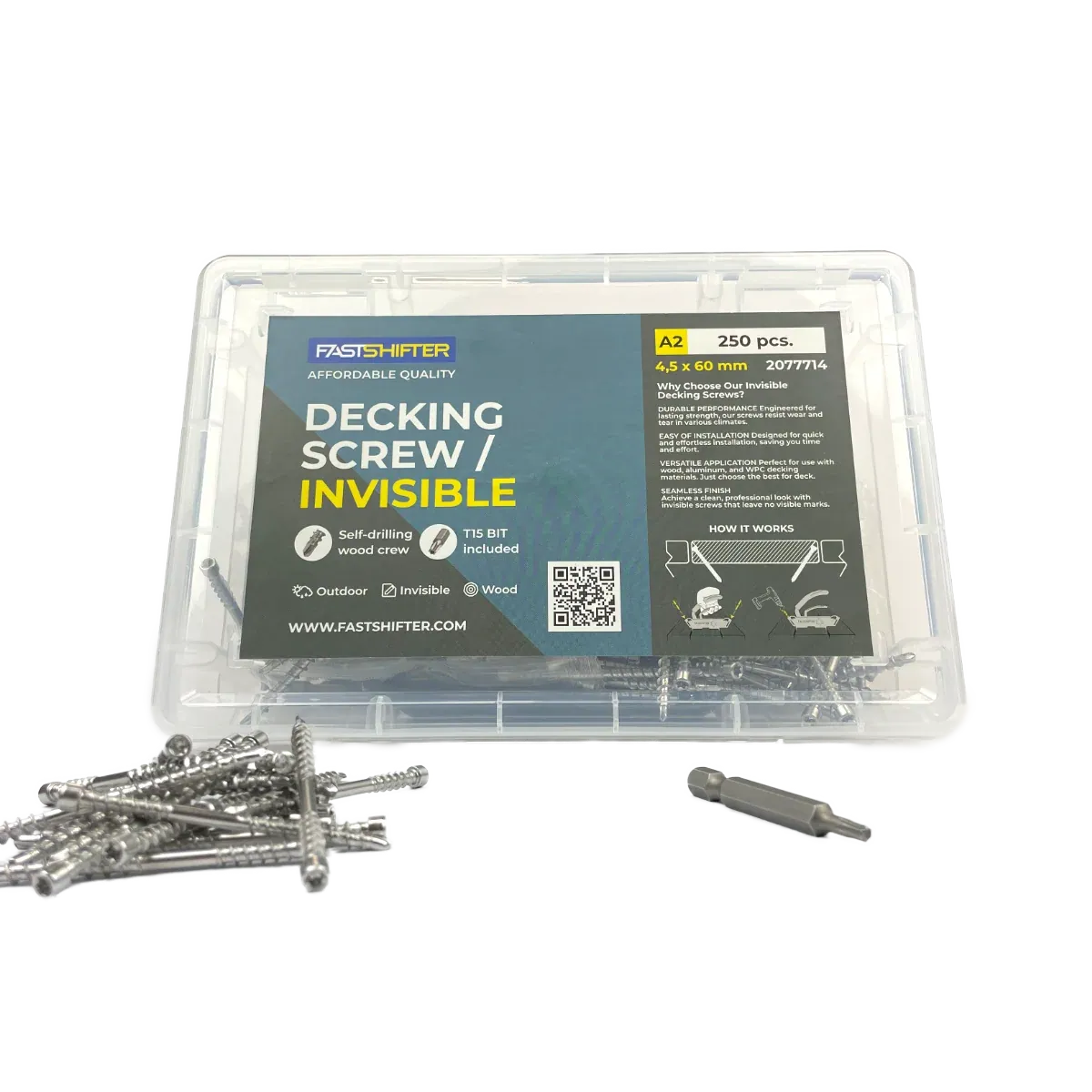
| Face screws | 2 per board per joist | 756 + spare → about 800–830 |
| Hidden edge screws | per system instructions, usually both edges at each joist | about 800–830 with spare |
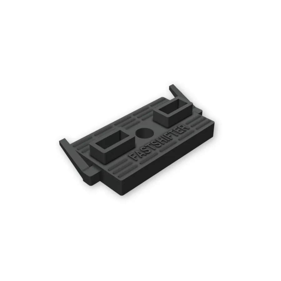
| Hidden clips | one per joist in each gap between boards: 26 gaps × 14 | 364 + first and last boards + spare |
| Spare | 5–10 % on all of the above | round up to full packs |
The pedestal figures are planning rates for Fastshifter FT pedestals, taken from how many pedestals per m², which also explains the single and double joist layouts in detail. They are not a structural design.
The method, step by step
Step 1: area and direction. Measure the deck and decide which way the boards run. The joists run at right angles to the boards. In the example, boards run along the 5 m side, so the joists are 4 m long and spread across 5 m.
Step 2: joists. Divide the width across the joists by the joist spacing, round up and add one for the second edge. Multiply by the joist length for running metres. Add a second joist wherever two board ends meet, and extra joists or blocking for borders, picture frames and steps.
Step 3: supports. Choose the layout. On a single layout every joist sits on its own supports; on a double layout the supports carry bearers and the joists cross on top. Apply the rate, then cross-check: joists × supports per joist from the span table. In the example, 60–70 pedestals spread over 14 joists means about 4–5 supports per 4 m joist. On soil, the same logic applies to ground screws: about one per m² on a double layout, with the exact number set by the frame spacing. For screw length by soil and frost depth, see ground screw length.
Step 4: heights. On a slab, measure the highest and lowest points. A fall of a few centimetres usually means two or three FT sizes, for example FT3 40–64 mm and FT4 64–110 mm. Split the count by zone rather than ordering one size for the whole deck.
Step 5: joist tape. Add up joist metres, plus bearer metres on a double layout, and divide by the roll length. The 50 mm butyl tape covers standard joists; use 80 mm over double joists and at board end joints. Allow for folding over the joist ends. Why it is worth it is covered in joist tape: why it matters.
Step 6: board fixings. Count crossings, not square metres: rows of boards × number of joists. Then apply the fixing method:
- Face screws: two per board at every joist. Edge boards, fascia and steps are often face-fixed even on a hidden-fixed deck, so count them separately.
- Hidden edge screws: follow the system instructions; boards are usually fixed on both edges at each joist. Fastshifter invisible screws come in 250 and 600 packs, for example one 600 pack plus one 250 pack for the example deck.
- Clips: only for grooved boards. Each clip sits between two neighbouring boards at a joist, held by one screw, so plan one clip per gap per joist and fix the first and last boards as the board maker specifies.
Treat these as rules of thumb and always follow the board manufacturer’s instructions on fixing pattern and spacing. For choosing the method, see hidden screws vs face screws vs clips; for the steel grade, A2, A4, C4 or SS410.
Step 7: frame connections. Count every joist-to-bearer and rim connection and use the structural fixing the frame design specifies. Do not estimate these per square metre.
Step 8: spares and packs. Add around 5–10 % to fixings, tape and supports, then round each line up to full packs. Doors, thresholds, steps, heavy planters and hot tubs need extra supports beyond the average rate.
Common mistakes on the material list
- Counting screws per m². Joist spacing and board width change the crossing count; always count rows × joists.
- Forgetting the bearers. On a double layout, bearers need tape and connections too.
- One pedestal size for the whole job. Slabs fall towards a drain; split the count by height.
- No spare. A few missing fixings can stop a crew for half a day.
FT pedestals are rated up to 800 kg each, and the C4 invisible screws are tested to 1500 hours of salt spray testing, but the binding limits on any deck remain the board span and the joist span table. For the bigger picture, read why the substructure matters more than the boards.
Quoting a project or building a range for your customers? Send us the deck size and board type at info@fastshifter.com and we will help you put the material list together, or request samples through the distributor form.
Frequently asked questions
How do I calculate how many joists a deck needs?
Divide the deck width across the joists by the joist spacing, round up to whole spaces and add one. For 5 m at 400 mm centres: 5000 ÷ 400 = 12.5, so 13 spaces and 14 joists. The spacing itself comes from the board maker's maximum span.
How many decking screws per m²?
Count crossings instead of square metres: board rows × joists. Face fixing uses two screws per board at every joist. On the 20 m² example with 145 mm boards that is 378 crossings and about 756 screws, before spares. Hidden screws and clips follow their own system instructions.
How much joist tape do I need?
Add up the length of every joist, plus bearers on a double layout, and divide by the roll length. Fourteen 4 m joists make 56 m, which is three 20 m rolls with almost nothing to spare, so order four. Use 80 mm tape where two board ends meet over one joist.
How many spares should I add?
Around 5–10 % on fixings, tape and supports, then round up to full packs. Thresholds, steps, edge boards and heavy planters usually need more supports and fixings than the average, and spares are cheaper than a stopped job.
Is this list a structural design?
No. It is a planning method for quoting and ordering. Joist profiles, support spacing and fixing patterns must follow the board maker's instructions and the joist supplier's span tables.